
Updated: 2026 Engineering Standard · By Sailwin Mold R&D Team
Plastic Injection Mold Design Guide: DFM Principles, Parting Lines & Ejection
Releasing a 3D CAD part model to tooling without rigorous Design for Manufacturability (DFM) analysis causes an estimated 70% of premature mold modifications, secondary rework costs averaging $6,000 to $18,000 per tool, and weeks of project delays. When engineering teams fail to master a practical injection mold design guide, subtle oversights—such as missing draft angles on deep ribs, non-uniform wall sections causing sink marks, or misaligned parting lines—inevitably translate into catastrophic sink marks, part warping, and high injection scrap rates.
At Sailwin, our mold design department has engineered over 1,500 custom tooling sets for high-speed rigid packaging, precision closures, and industrial housings. We have proven that optimizing parting lines, gating symmetry, and cooling jacket conformal flows during the digital simulation phase reduces physical tool commissioning iterations by more than 80%.
This comprehensive technical guide outlines the exact mathematical criteria, tolerance boundaries, and mechanical design rules required to transform raw component CAD files into high-yield, long-life production injection molds.
Key Takeaways
- Strict Draft Standards Eliminate Scuffing: A minimum of 0.5° to 1.0° draft per side is non-negotiable for polished vertical ribs, while textured EDM surfaces demand an additional 1.5° per 0.025mm of depth to prevent part drag marks and vacuum sticking.
- Nominal Wall Uniformity Rules: Maintaining wall thickness variation within ±15% of the nominal dimension prevents differential thermal shrinkage, eliminating post-ejection part warpage and localized cosmetic sink marks.
- Conformal Cooling Advantage: 3D-printed metal conformal cooling channels integrated into deep cavity cores reduce thermal cycle times by 30% to 45% compared to traditional straight gun-drilled baffles.
Have a new plastic part drawing ready for tooling evaluation?
Submit your 3D CAD files (STEP/IGS) to Sailwin for a complimentary 24-hour Moldflow simulation report.
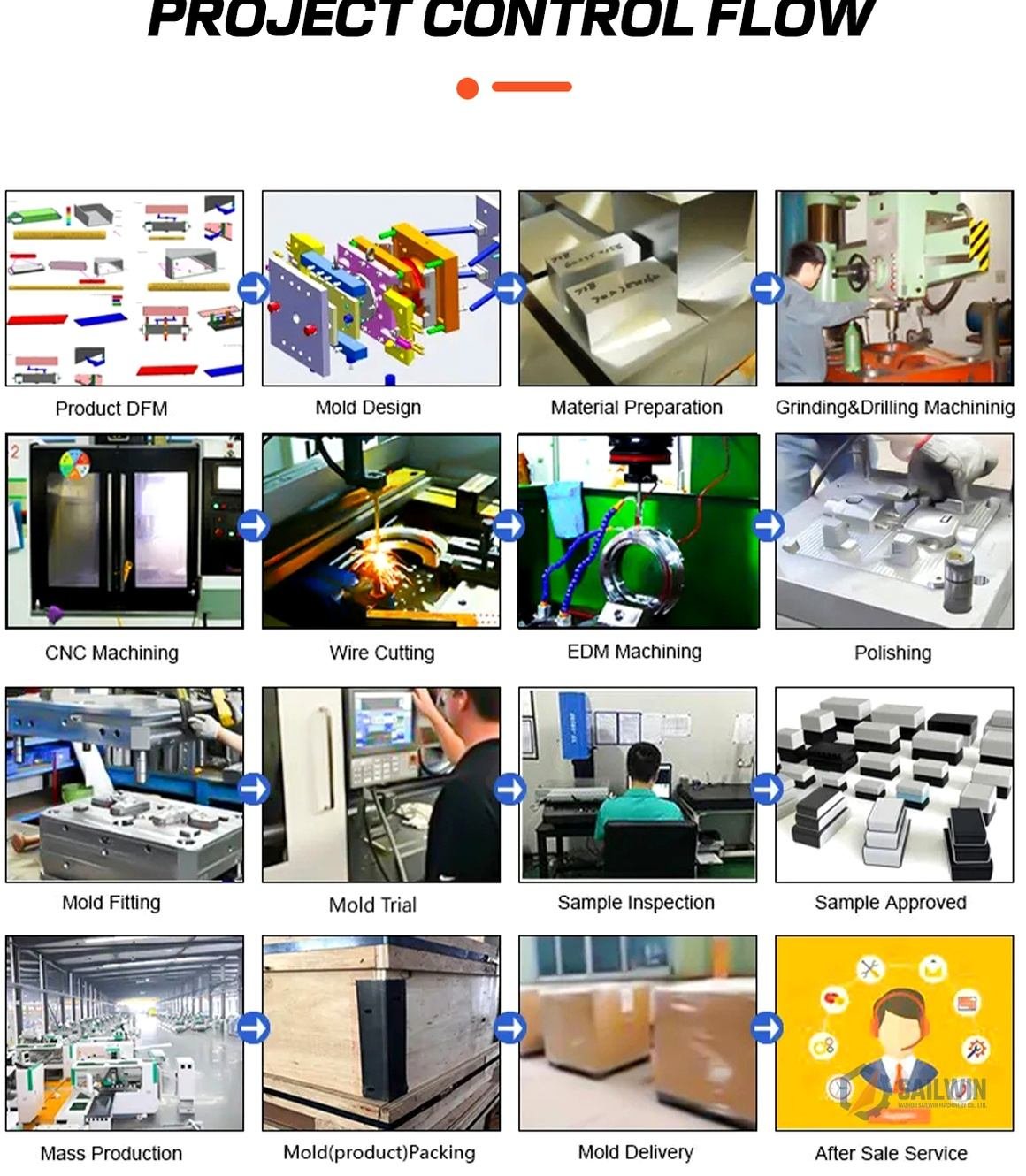
1. Core DFM Checklist: 5 Geometric Rules Before Cutting Tool Steel
A thorough injection mold design guide mandates that part geometry must adapt to thermal contraction, hydraulic clamp pressures, and ejection physics. Over 85% of molding defects originate from part modeling violations rather than machine processing faults.
1. Nominal Wall Thickness & Coring-Out Practice
Thick solid plastic sections cool far slower than thin outer walls, pulling molten material inward during cooling to form unsightly sink marks or internal structural voids. For standard polymers like polypropylene (PP) and polyethylene (PE), nominal walls should sit between 1.2mm and 2.8mm. Heavy bosses and structural ribs must be cored out and limited to 50% to 60% of the adjacent wall thickness to guarantee zero cosmetic depression on the aesthetic Class-A surface.
2. Draft Angles for Clean Ejection Without Drag Marks
As polymer cools in the mold, it shrinks away from the outer cavity steel and locks tightly onto the inner core pins. Without sufficient taper, the mechanical force of ejector pins will buckle the plastic or leave deep vertical scratch marks. Smooth polished surfaces require at least 1.0° of draft angle per side; deep textured or spark-eroded ribs require 3.0° to 5.0° to release cleanly.
3. Radius & Stress Concentration Transitions
Sharp 90-degree internal corners act as catastrophic stress intensifiers during both injection filling and customer usage. A minimum internal fillet radius of 25% to 50% of the nominal wall thickness (minimum 0.5mm) must be designed into every corner. Radiused corners reduce polymer flow resistance, lower hydraulic pressure drop by up to 22%, and increase structural drop impact resistance by 300%.
| Resin Material | Shrinkage Rate (%) | Nominal Wall (mm) | Min Draft Angle | Max Rib-to-Wall Ratio |
|---|---|---|---|---|
| Polypropylene (PP) | 1.5% – 2.2% | 0.9 – 2.5 mm | 1.0° (Core) / 0.5° (Cavity) | 50% |
| Polyethylene (HDPE) | 1.8% – 3.0% | 1.0 – 3.0 mm | 1.5° (Core) / 1.0° (Cavity) | 50% |
| PET (Polyethylene Terephthalate) | 0.2% – 0.5% (Preform) | 1.5 – 4.5 mm | 0.5° – 1.0° | 40% |
| ABS / PC-ABS Alloy | 0.4% – 0.7% | 1.5 – 3.2 mm | 1.0° (Smooth) / 3.0° (Texture) | 60% |
For complex closure applications like our flip-top cap mold systems, balancing living hinge thickness (typically 0.35mm) with the main lid skirt is critical to ensure proper resin orientation.
Designing a complex closure or packaging mold?
Consult Sailwin’s tooling architects for gate location analysis and cooling line balance calculations.
2. Parting Line Placement, Gating Architectures & Flow Balancing
The parting line dictates mold manufacturing cost, flash propensity, and aesthetic witness lines. Selecting between submarine edge gates, direct pin-point gates, or needle valve-gate hot runners determines whether your part requires costly manual post-trimming.
Parting Line Optimization Strategies
Tooling engineers must position the parting line across the largest cross-sectional perimeter of the component. Flat, planar parting lines allow for high-speed CNC surface grinding, reducing tooling build costs by 20% compared to stepped or contoured 3D parting surfaces. If flash occurs, as detailed in our guide on fixing plastic injection molding flash, parting line wear is generally the culprit.
Gating Selection Matrix: Edge vs Submarine vs Valve Gate
- Direct Sprue Gate: Simplest configuration with low pressure drop, but leaves a large vestige that requires manual clipping; restricted to single-cavity industrial buckets.
- Submarine (Tunnel) Gate: Automatically shears the runner from the part during mold opening, dropping parts and scrap into separate chutes without human intervention.
- Valve-Gate Hot Runner: The ultimate standard for high-cavity packaging, closures, and valve-gate preform molds. Pneumatic or hydraulic shut-off pins leave a near-invisible gate vestige (<0.05mm) with zero plastic scrap.
Need help choosing between cold runner and valve-gate tooling?
We calculate resin savings and payback timelines for 16, 24, 32, and 48-cavity configurations.
3. Ejection Mechanisms: Stripper Plates, Lifters & Hydraulic Cores
Ejector system design balances mechanical ejection force against hot plastic rigidity. Improper ejector pin sizing causes white punch marks (stress whitening) or part puncturing, causing automatic production line shutdowns.
In packaging closures (such as bottle cap injection mold tooling), round ejector pins cannot be used because they would deform the circular sealing band. Instead, moldmakers specify full perimeter stripper rings (stripper plates) that advance uniformly, pushing the entire rim of the cap off the core with zero local stress.
When molding external side undercuts, mechanical angle lifters or hydraulic cylinder-actuated slide blocks must be incorporated. To evaluate total mold pricing implications for these complex mechanisms, explore our comprehensive breakdown on plastic injection mold cost calculation.
4. Sailwin Case Study: DFM Optimization Cuts Automotive Housing Cycle by 28%
A Tier-1 automotive connector supplier reduced part rejection rates from 14% to 0.2% after Sailwin restructured the DFM gate positioning, cored out excessive boss mass, and introduced high-hardness S136 core inserts.
- Client: Manufacturer producing high-amperage fuse boxes in 30% glass-filled PA66.
- Initial Problem: Severe part warpage (1.4mm bow across 180mm length) and intense ejector pin puncture marks.
- Failure Cause: Non-uniform 3.8mm thick wall sections adjacent to 1.2mm perimeter walls, combined with unbalanced edge gating.
- DFM Redesign: Re-engineered internal rib structure to uniform 1.8mm nominal thickness with 0.8mm coring pockets.
- Gating Overhaul: Replaced single cold sprue with a 2-drop sequential pneumatic valve-gate hot runner.
- Ejection Upgrade: Swapped 12 small round pins for contoured blade ejectors aligned with deep reinforcing gussets.
- Part Warpage: Reduced from 1.40mm down to 0.12mm (well within OEM ±0.20mm tolerance).
- Cycle Time: Slashed from 36.5s to 26.2s (28.2% throughput increase).
- Tool Lifespan: Tool completed 1,800,000 cycles with zero cavity steel erosion.
Data source: Sailwin Engineering Case File #DFM-2025-08. Component: 180mm PA66-GF30 Automotive Distribution Module.
Experiencing part warpage or sink marks on an existing tool?
Send us your defective part photos and mold layout for a comprehensive engineering redesign proposal.
5. Frequently Asked Questions: Injection Mold Design Guide
Need immediate engineering feedback on your mold layout?
Connect directly with Sailwin’s technical tooling team on WhatsApp for fast drawing reviews.
6. Summary: Building Defect-Free Production Tooling
Flawless plastic injection molding begins long before steel is loaded into CNC machining centers. Adhering to strict DFM principles—uniform walls, adequate draft, balanced gating, and optimized thermal management—is the most cost-effective investment in your product’s lifecycle.
- Never compromise on nominal wall uniformity; coring out heavy bosses eliminates cosmetic sinks and speeds up cycle cooling.
- Choose parting lines that minimize side-action slider complexity and hide witness seams along natural cosmetic edges.
- Partner with an experienced mold engineering manufacturer who performs comprehensive Moldflow simulation before steel release.
SAILWIN TOOLING · DFM EXCELLENCE
Ready to Transform Your CAD Drawing Into Production Tooling?
Upload your 3D CAD files (STEP / IGS) or technical component prints. Our senior mold design engineers will deliver a comprehensive DFM audit, parting line layout, and turnkey tooling quote within 24 hours.
Explore Precision Tooling & Mold Systems:
• plastic injection molds – Comprehensive industrial tooling from prototype to 96-cavity packaging.
• valve-gate preform molds – High-speed PET preform tooling with sub-0.08mm eccentricity.
• bottle cap injection mold – 1881 & 3025 closure molds with cycle times under 9.5 seconds.
• flip-top cap mold – In-mold closing butterfly hinge tooling systems.
• rotary cap assembling machine – Downstream multi-piece closure automation systems.
• cap lining and wadding machine – High-speed liner insertion and wadding equipment.
• Need dedicated technical consultation? Contact our mold design engineers for 1-on-1 CAD review.

