
Updated: 2026 Tooling Guide · By Sailwin Mold Engineering Team
How to Fix Plastic Injection Molding Flash Defects: Causes & Tooling Solutions
Persistent parting line flash is one of the most frustrating and costly quality failures in high-volume plastic production, driving up manual deflashing labor expenses by $0.02 to $0.08 per part while accelerating tool steel erosion. When quality inspectors report plastic injection molding flash, molding technicians frequently respond by simply jacking up machine clamp tonnage—a band-aid reaction that permanently crushes delicate parting line vents, indents mold plates, and destroys core shut-off angles.
With over two decades of precision toolmaking experience across high-pressure packaging closures and precision medical housings, Sailwin approaches flash eradication through systematic root-cause diagnosis. Whether flash originates from machine hydraulic platen deflection, V/P changeover lag, or physical parting line debris indentations, understanding the mechanical shut-off dynamics restores clean, flash-free production.
This technical troubleshooting guide provides processing technicians and toolroom managers with a step-by-step diagnostic roadmap—covering machine process optimization, parting line spotting, laser micro-welding repair, and mold structural stiffening.
Key Takeaways
- Parting Line Clearance Threshold: Molten polypropylene, polyethylene, and polystyrene will flash whenever parting clearance exceeds 0.020mm (20 microns), while low-viscosity resins like PA66 flash at clearances as tight as 0.010mm.
- V/P Switchover Timing Is Critical: Over-packing cavities by delaying the velocity-to-pressure switchover spikes internal mold pressure above 800 bar, momentarily springing open machine platens and generating parting flash.
- Support Pillars Prevent Center Deflection: In multi-cavity tooling, adding hardened support pillars directly beneath cavity backing plates reduces platen flex by up to 85%, eliminating chronic center-row flash.
Struggling with persistent parting line flash on your molds?
Send high-res defect photos and mold layouts to Sailwin for an immediate technical assessment.
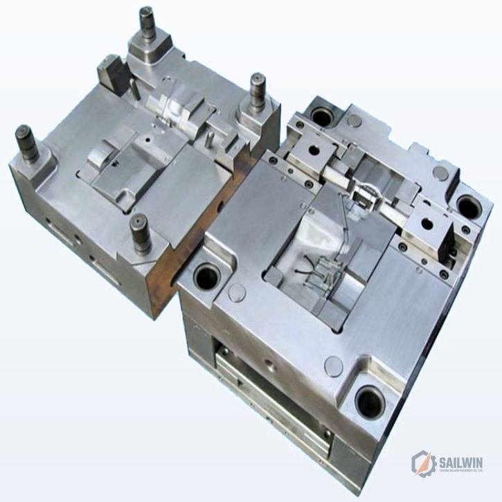
1. Processing Parameter Diagnostics: Eliminating Flash at the Machine Screen
Before pulling a mold from the press for expensive toolroom machining, 60% of flash issues can be resolved through scientific molding adjustments: optimizing V/P switchover position, balancing melt viscosity, and calibrating projected clamp tonnage.
Step 1: Verify Clamping Tonnage Calculation
Clamping tonnage must comfortably exceed total cavity projected area multiplied by peak cavity pressure. As a benchmark, polyolefins require 2.5 to 3.5 tons per square inch of projected area, while high-flow engineering resins require 4.0 to 5.5 tons/sq.in. If total projected area of your parts and runner system is 120 sq.in., running on a 300-ton press creates marginal clamp margin that invites parting line separation.
Step 2: Calibrate Velocity-to-Pressure (V/P) Switchover
The primary process cause of flashing is over-packing during dynamic velocity fill. The injection forward stroke must switch to holding pressure when cavities are 95% to 98% volumetrically full. If switchover occurs late, the machine delivers full booster velocity against a dead-end cavity, generating an intense pressure surge that bursts past parting seals.
Step 3: Melt Temperature and Viscosity Control
Excessive barrel temperatures dramatically reduce polymer melt viscosity. A superheated polymer behaves like water, easily seeping into microscopic venting channels and slider shut-off clearances. Lowering barrel temps by 10°C to 15°C increases melt strength and eliminates flash without degrading part weld line strength.
| Flash Symptom | Probable Root Cause | Immediate Process Remedy | Permanent Tooling Fix |
|---|---|---|---|
| Flash on Entire Perimeter | Insufficient clamp tonnage or late V/P switch | Shift V/P switch earlier (to 95% full); reduce pack pressure | Transfer mold to larger tonnage press; verify platen parallelism |
| Localized Parting Flash | Plastic debris crushed on parting land or dented steel | Clean parting surface with copper scraper; re-spot dye | Precision laser micro-weld crushed area and stone flat |
| Flash in Center Cavities Only | Mold base plate deflection under injection pressure | Lower peak injection speed and injection hold time | Install hardened support pillars (SP) beneath cavity block |
| Flash on Moving Slides | Worn heel blocks, loose gibs, or angle pin play | Inspect slider mechanical lock pre-load (0.03mm interference) | Shim heel lock block or machine new wear plates |
Need mold maintenance or laser welding repair services?
Sailwin’s toolroom engineers provide precision mold refurbishing, parting re-spotting, and shut-off recutting.
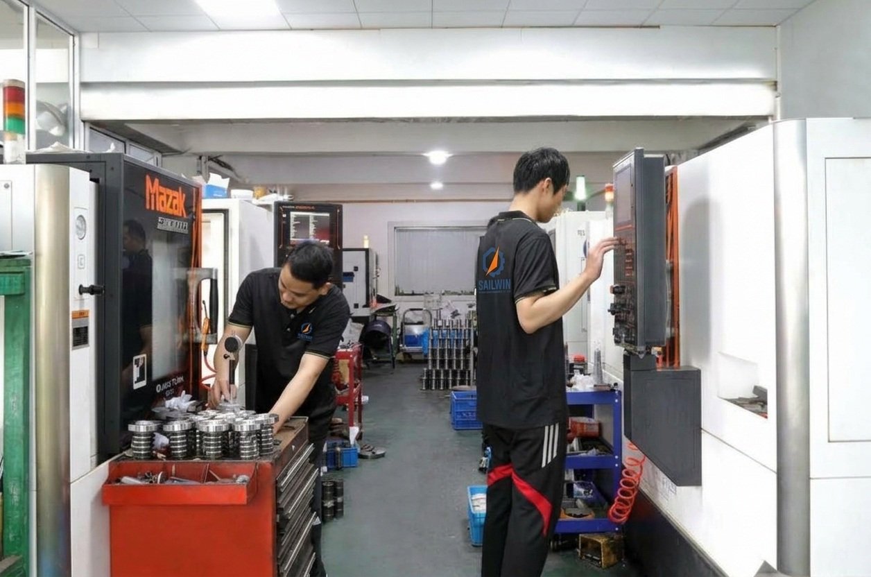
2. Toolroom Mechanical Repairs: Blue-Dye Spotting & Laser Welding
When mechanical wear exceeds 0.02mm, no processing trick can overcome physical steel gaps. Precision moldmakers use blue spotting dye and laser deposition welding to rebuild damaged parting lands without softening base metal hardness.
Parting Land Blue-Dye Spotting Protocol
Tool technicians coat one mold half with an ultra-thin (0.005mm) film of Prussian blue paste, close the tool under low clamp tonnage on a spotting press, and inspect the transfer pattern. High-quality plastic injection molds must exhibit at least 90% to 95% uniform contact coverage across all shut-off perimeters. High spots must be carefully stoned down, while low areas require weld build-up.
Venting Channel Depth vs. Plastic Burning
Often, flash occurs because operators try to eliminate burns (dieseling) caused by clogged or undersized vents. If vents are made too deep (>0.035mm for PP), air escapes but plastic follows, creating flash. The golden rule is: vent land depth must be 0.015mm – 0.025mm for polyolefins and 0.010mm for PA66, transitioning into a 0.8mm deep exhaust trench after a 3.0mm land length.
3. Sailwin Case Study: Eliminating Flash on a 32-Cavity Water Cap Mold
A high-volume mineral water bottler was rejecting 6.5% of closures due to razor-sharp tamper band flash that failed downstream cap slitting and folding machine operations.
- Client: Beverage bottler producing 28mm PCO1881 HDPE caps on a 32-cavity mold.
- Problem: 0.15mm parting line flash on inner sealing ribs after 800,000 cycles, causing downstream capper slippage.
- Prior Attempts: Client increased clamping tonnage from 220T to 280T, which indented cavity vents and caused black burn marks.
- CMM Inspection: Identified 0.035mm plate deflection in the center 8 cavities due to lack of center support pillars.
- Laser Refurbishing: Deposited H13 tool steel wire on crushed venting lands, micro-milling back to 0.018mm depth.
- Mechanical Stiffening: Added 4 hardened Ø60mm support pillars (SP) directly behind center core blocks.
- Parting Line Flash: Completely eliminated (parting line burr < 0.008mm, well within QA limits).
- Clamp Tonnage: Reduced back to 210 tons, cutting machine electrical draw by 14%.
- Scrap Rate: Dropped from 6.5% to 0.04%, saving $31,000 in monthly resin and downtime losses.
Data source: Sailwin Service Report #FL-2025-11. Tooling: 32-Cavity High-Speed Water Closure Mold SW-32CAP.
Need custom bottle cap or preform tooling with zero flash guarantees?
Explore Sailwin’s factory-direct multi-cavity tooling engineered with vacuum-heat-treated S136 stainless steel.
4. Frequently Asked Questions: Fixing Injection Molding Flash
Facing recurring flash defects on critical parts?
Connect with Sailwin’s toolroom engineers for immediate remote troubleshooting advice on WhatsApp.
5. Summary: Eliminating Flash for Uninterrupted Production
Parting line flash is never acceptable in high-efficiency injection manufacturing. Addressing process parameters systematically—first checking V/P transition and clamping tonnage before proceeding to mechanical spotting and laser weld refurbishing—protects your tooling capitalization and delivers zero-defect parts.
- Never solve flash by simply overloading clamp tonnage, which permanently destroys mold air venting.
- Ensure parting land contact exceeds 90% across all cavity shut-off lands using blue-dye spotting checks.
- Consult with Sailwin Tooling for precision mold refurbishment, laser restoration, and high-rigidity mold bases.
SAILWIN TOOLING · PRECISION REFURBISHING
Ready to Eliminate Flash and Restore Mold Yields?
Upload your component drawings or send photos of your parting line flash defects. Our master toolmakers will deliver a comprehensive mold refurbishing and process optimization plan within 24 hours.
Explore Precision Tooling & Mold Systems:
• plastic injection molds – Comprehensive industrial tooling from prototype to 96-cavity packaging.
• bottle cap injection mold – 1881 & 3025 closure molds with cycle times under 9.5 seconds.
• medical child-resistant cap mold – Ultra-tight tolerance CRC closure tooling systems.
• cap slitting and folding machine – High-speed rotary tamper-evident ring cutting cells.
• injection mold design guide – DFM principles for draft angles, parting lines, and ejection.
• plastic injection mold cost calculation – 2026 pricing breakdown for tooling steels and cavities.
• Need dedicated technical consultation? Contact our tooling engineers for personalized DFM consultation.

